

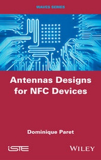
Antennas Designs for NFC Devices
Erschienen am 5. Januar 2016
344 Seiten
978-1-119-14531-8 (ISBN)
Beschreibung

Near-field communication (NFC) enables the exchange of information between close devices.
The antenna is the indispensable element to transform an electronic device into an NFC system. For both theory and practice, this book presents in detail the design technologies of different antennas. They must meet the NFC ISO 18 092 and 21 481 standards as well as specifications by the NFC Forum for industrial applications, by EMVCo for banking applications and payments, and by CEN for public transport.
In a particularly pedagogic way, Antenna Designs for NFC Devices enables designers of communicating object systems and the Internet of Things (IoT) to have access to the mysteries of the design of NFC antennas.
Weitere Details
Weitere Ausgaben
Andere Ausgaben
Dominique Paret
Antenna Designs for NFC Devices
Buch
01/2016
1. Auflage
Wiley-ISTE
163,50 €
Versand in 15-20 Tagen
D. Paret
Antenna Designs for NFC Devices
Software
01/2016
Wiley
173,40 €
Keine Lieferinformation verfügbar
Person
Dominique Paret is a consultant in radiofrequency identification, contactless technologies, NFC and indoor geolocalization. He teaches electronics and RFID in various engineering schools. He is also the author of several books on RFID technologies.
Inhalt
- Cover
- Title Page
- Copyright
- Contents
- Acknowledgments
- Preface
- Why this book?
- For whom?
- Warning
- Introduction
- PART 1: Context
- Introduction to Part 1
- Chapter 1: Recap of the Constraints Governing the Design of Antennas for an NFC Device
- 1.1. Normative constraints
- 1.1.1. Uplink from initiator to targets
- 1.1.2. Downlink from targets to initiator
- 1.1.2.1. "Passive" targets
- 1.1.2.2. "Active" targets
- 1.1.2.3. Load modulation
- 1.1.2.4. Retro-modulation voltage
- 1.1.2.5. Retro-modulation voltage in PLM
- 1.1.3. "Contactless" standards versus NFC device antennas
- 1.1.4. Technologies
- 1.1.4.1. NFC-A technology
- 1.1.4.2. NFC-B technology
- 1.1.4.3. NFC-F technology
- 1.1.5. "NFC Forum Devices" and "NFC Forum Tags"
- 1.1.5.1. NFC device
- 1.1.5.2. NFC Forum Devices
- 1.1.5.3. NFC Forum Tags
- 1.1.6. Modes of communication of an NFC Forum Device
- 1.1.6.1. Passive communication mode
- 1.1.6.2. Active communication mode
- 1.1.7. Role of an NFC Forum Device
- 1.1.7.1. Initiator
- 1.1.7.2. Reader/writer
- 1.1.7.3. Target
- 1.1.7.4. Card emulator
- 1.1.8. Beware of false advertising
- 1.2. Regulatory constraints
- 1.2.1. RF regulations
- 1.3. Constraints on the NFC market
- 1.4. Typological constraints of NFC
- 1.4.1. Application consequences and their direct constraints
- 1.5. Applicational constraints on antenna design
- Chapter 2: Introduction to and Recap of the Principles Employed in NFC
- 2.1. The physical fundaments of "contactless" and NFC
- 2.1.1. Phenomenon of propagation and radiation
- 2.1.2. Classification of fields and spatial regions
- 2.1.3. Spatial regions
- 2.1.4. Far field: r && ?/2p (Fraunhofer zone)
- 2.1.5. Intermediary field: r approximately equal to ? (Fresnel zone)
- 2.1.6. Near field: r && ?/2p (Rayleigh zone) . and by essence, the origin of the "NF - Near Field", and hence NFC
- 2.1.7. Remarks on contactless, RFID and NFC application
- 2.2. The concept of NFC
- 2.2.1. Biot-Savart law
- 2.2.2. Field H at a point on the axis of a circular antenna
- 2.2.3. Decrease in the field H as a function of "d"
- 2.2.4. Field H at a point on the axis of a rectangular antenna
- PART 2: Methods and Designs for NFC Device Antennas
- Introduction to Part 2
- Acknowledgments
- Chapter 3: "Initiator" Antennas: Detailed Calculations
- 3.1. Introduction
- 3.1.1. There are initiators . and there are initiators
- 3.2. Design of an initiator antenna (without influence from the outside environment)
- 3.2.1. Operating mode
- 3.2.2. Instructive recap
- 3.2.2.1. Conditions of power matching of a source/generator
- 3.2.2.1.1. Case where the internal impedance and the load are pure resistances
- 3.2.2.2. A little stronger
- 3.2.2.3. Ever stronger
- 3.2.2.3.1. What is the value of the current in the circuit? Good question
- 3.2.2.3.2. What about the output voltage from the integrated circuit?
- 3.2.2.3.3. What about the voltage at the terminals of the L, C circuit?
- 3.2.3. Choice of integrated circuit
- 3.2.3.1. "Single-ended" output
- 3.2.3.2. "Differential mode" output
- 3.2.3.3. Conclusions
- 3.2.4. Legislational constraining aspects and EMC pollution
- 3.2.5. EMC filtering
- 3.2.5.1. Filtering circuit
- 3.2.5.2. Tuning frequency of the filter
- 3.2.5.3. Condition for transferring maximum watt power to a load Rp
- 3.2.5.3.1. Calculation of the impedance "Z_in_filter"
- 3.2.5.3.2. Example of simulation of the filtering LC circuit on its own(R_ic_out = 12.5O - single-ended)
- 3.2.5.4. Current circulating in the resistance Rp
- 3.2.5.5. Power dissipated into the resistance Rp
- 3.2.5.5.1. Overall summary for the "EMC filter" circuit
- 3.2.6. Choice of target used and incidence of its H_threshold
- 3.2.6.1. Estimation of the field H which needs to be produced by the initiator antenna
- 3.2.6.2. Example of application for a specific target
- 3.2.7. Determining the inductance value of the initiator antenna
- 3.2.7.1. Value of maximum current in the initiator antenna
- 3.2.7.2. In conclusion
- 3.2.7.3. Constraints imposed on antenna design
- 3.2.8. Simple antenna
- 3.2.8.1. Flat circular coil
- 3.2.8.2. Flat rectangular coil
- 3.2.8.3. A few remarks on the content of the table
- 3.2.9. Matching circuit for the impedance of the antenna
- 3.2.9.1. Determination of the impedance-matching capacitance bridge
- 3.2.9.2. Calculating the matching elements of the antenna
- 3.2.10. Calculating the current in the antenna coil of the initiator
- 3.2.11. Summary and examples
- 3.2.11.1. Application without an EMC filter
- 3.2.11.2. Example of application with an EMC filter and R_in =12.5 ohms
- 3.2.12. Simulations
- 3.2.12.1. Application with an EMC filter
- 3.2.12.2. Final example of simulation with second filtering LC circuit
- 3.2.13. Value of the field H radiated by the antenna
- 3.2.14. Calculation and value of the working distance
- 3.3. Maximum quality coefficient Q of the initiator antenna
- 3.3.1. Q and cutoff of the field
- 3.3.2. Decrease in the ISO field
- 3.3.3. Measuring Q in the application
- 3.3.4. Measurement of the bandwidth in the application
- 3.4. Brief handbook on the process of designing an antenna initiator
- Chapter 4: Examples of Applications of Initiator Antennas
- 4.1. Large antennas
- 4.1.1. Communication with a mono-NFC device in "card emulation - battery-assisted" mode
- 4.1.2. Communication multi-NFC devices in "tag batteryless" mode
- 4.2. Large antenna in mono-device
- 4.2.1. Mechanical formats of the NFC device targets
- 4.2.2. "Form factors" and sizes of antennas of the targets
- 4.2.3. Application distances required for operation
- 4.2.4. Estimation of the "loading effects" of the distance or working range
- 4.2.5. Environment (copper, ferrite, battery, etc.)
- 4.2.6. Several measures for illustrating our proposal
- 4.2.7. H_d field necessary for the NFC device target
- 4.2.8. H_0 necessary to create at the antenna level of the initiator
- 4.2.9. Power P (in watts)
- 4.2.10. Field H which must be produced by the initiator for a specific target
- 4.2.11. Definition of the initiator antenna: format of the "landing area" of the reader (where one puts the target)
- 4.2.12. "System" considerations of the application
- 4.2.12.1. Quality Q coefficient
- 4.2.13. Market integrated circuits for direct attack of the antenna
- 4.2.13.1. Existing R_ic_out resistance values
- 4.2.13.2. Necessary R_ic_out resistance values
- 4.2.13.3. Conclusions
- 4.2.14. Booster amplifiers
- 4.2.14.1. Booster amplifier in discrete components
- 4.2.14.1.1. Conclusion
- 4.2.14.2. Booster amplifier in class C
- 4.2.14.3. Booster amplifier in integrated circuits
- 4.2.14.3.1. AM 3911 and AS3911B
- 4.2.14.3.2. AM 39230
- 4.2.15. Problem of the retro-modulation value
- 4.2.15.1. Amplify the signal received/preamplifier stage
- 4.3. Large antennas in multi-antennas
- 4.3.1. In simultaneous mode (temporarily non-multiplexed)
- 4.3.1.1. Division of the mono-antenna of the initiator in "n" antennas
- 4.3.1.1.1. Flow addition and subtraction problems and zones of "zerolines"
- 4.3.1.1.2. Incidences due to voluntary or involuntary coupling of the antennas belonging to the same branch or to neighboring branches
- 4.3.1.2. Division of the antenna in 2 or "n x n" antennas in parallelseries mounting
- 4.3.1.3. Conclusions
- 4.3.2. In multiplexed mode temporarily
- 4.3.2.1. Temporarily multiplexed antenna network
- 4.3.2.2. Temporarrily multiplexed antennaa network with cover
- 4.4. Large antennas in multi-devices
- 4.4.1. Conclusions
- 4.5. Other examples of initiator antennas
- Chapter 5: Antennas for Targets and Tags: Detailed Calculations
- 5.1. Introduction: there is a target and target
- 5.2. NFC Forum Tags
- 5.2.1. "Technology Subset"
- 5.3. Introduction to problems of antenna targets/tags
- 5.3.1. Tuning of the targets/tags
- 5.3.2. The inductance L
- 5.3.2.1. The capacity C
- 5.3.2.1.1. Nominal value
- 5.3.2.1.2. Precision
- 5.3.2.1.3. Capacity electric performances
- 5.3.2.1.4. Performance measurements
- 5.3.2.2. Application fields and uses of additional capacities
- 5.3.2.2.1. Economic aspects
- 5.4. State-of-the-art of the antenna sizes
- 5.4.1. Sizes of the target antennas
- 5.4.1.1. ISO 14 443 antenna classes
- 5.4.2. Examples of applications of targets with antennas in ISO classes
- 5.4.2.1. Class 1
- 5.4.2.2. Class 2
- 5.4.2.3. Classes 3, 4 and 5
- 5.4.2.4. Class 6
- 5.4.2.5. NFC antenna formats outside ISO 14443
- 5.4.2.6. Associated values of the magnetic H fields
- 5.4.2.6.1. Some complements concerning how to measure these magnetic fields
- 5.4.2.7. Calculation of the fields and magnetic inductions of a minimum threshold
- 5.4.2.7.1. Electric representation of the target
- 5.4.2.8. Magnetic field of minimum threshold
- 5.4.2.8.1. Specific case or the target is strictly fine tuned
- 5.5. Technological aspect of the NFC targets and tags
- 5.5.1. Data specific to integrated circuits for usage by NFC targets
- 5.5.2. Data specific to the additional capacities
- 5.5.3. Industrial data specific to antenna technology
- 5.5.4. Technology at stake
- 5.5.4.1. Manufacturing technology of the antenna winding
- 5.5.4.1.1. Antenna winding with the help of copper or aluminum wires
- 5.5.4.1.2. Etched antennas ("etched")
- 5.5.4.1.3. Printed antennas performed with the help of a deposit of conductor ink
- 5.5.4.1.4. Antennas carried out by heliogravure or by an offset process
- 5.5.4.2. Connection technology of the integrated circuit and/or report of the chip
- 5.5.4.2.1. Soldering
- 5.5.4.2.2. Bonding
- 5.5.4.2.3. Flip chips
- 5.5.4.3. Technology of the bridge(s)
- 5.5.4.3.1. Case of single-sided printed circuit
- 5.5.4.3.2. Case of double-sided printed circuit
- 5.5.4.3.3. In summary
- 5.5.4.3.4. Geometric forms of the winding
- 5.5.5. Estimation of the minimum number of antenna coils of the target to guarantee its remote power supply
- Chapter 6: Detailed Examples of Designs of Target Antennas
- 6.1. Case of small antennas
- 6.1.1. Examples in classes 4, 5, 6. or close by
- 6.1.2. Example of design in class 5
- 6.1.2.1. Connected objects (watch bracelet, etc. or of sport)
- 6.1.2.2. Examples of realization possibilities in class 5
- 6.1.2.2.1. Microcase with C = 30 pf therefore L = 4.6 µH
- 6.1.2.2.2. Microcase with C = 60 pF therefore L = 2.3 µH likewise
- 6.1.2.3. Calculation of the fields and magnetic inductions of a minimum threshold
- 6.1.2.4. If that does not happen
- 6.1.3. Example
- 6.1.3.1. Examples of optimization calculations of Qp2 and H_d_threshold
- 6.1.4. Example of design in class 6
- 6.1.4.1. In mini-rectangle (example minicard SIM) (Figure 6.3)
- 6.1.4.2. In mini-circle of F = 10 mm (Figure 6.4)
- 6.1.4.3. In mini-circle of F = 10 mm (Figure 6.5)
- 6.1.4.4. NFC applications for the luxury products anti-counterfeiting struggle
- 6.1.4.4.1. Some technology
- 6.2. Case of very small antennas
- 6.2.1. Example of design in classes 11, 12, 13
- 6.2.1.1. Determination of the inductance value of the "winding + ferrite"
- 6.2.1.1.1. Air core coil - Lo
- 6.2.1.1.2. Coils with ferrite - L
- 6.2.1.2. Together "antenna circuit of the integrated transponder/ circuit"
- 6.2.1.3. External/commercial data sheet tag
- 6.3. Case of the large NFC target/tag antennas: format A4
- 6.3.1. NFC bib number antennas for marathon and triathlon runners
- 6.3.2. Technical properties required by the NFC target/tag
- 6.4. Case of very large antennas targets: format A3
- 6.4.1. Context and technical frame of the large antennas
- 6.4.2. R Retained co oncept
- 6.4.2.1. From the manufacturer of the mobile telephone
- 6.4.2.2. From the manufacturer of photo frames/tablets
- 6.4.2.3. Determination of the nominal inductance value "L" of the antenna
- 6.4.2.3.1. For the antenna of the tag
- 6.4.2.3.2. For the integrated circuit
- 6.4.2.4. Parasite capacity of the antenna coil
- 6.4.2.5. Network of antennas
- 6.4.3. Example of network with four antennas
- 6.4.3.1. Hypothesis no. 1
- 6.4.3.2. Hypothesis no. 2
- 6.4.3.2.1. The two antennas belong to the same connection
- 6.4.3.2.2. The two antennas belong to two different connections
- 6.4.4. Simplification of the equation
- 6.4.4.1. Generalization with a network at "n²" (2, 4, 9, etc.) antennas
- 6.4.4.2. The sequence
- 6.4.4.3. Estimation of the tag antenna minimum surface, "Ae" to recover the necessary flow to the requirements of the application
- 6.4.4.4. Application in the NFC frame/tablet
- 6.4.4.5. Relations between magnetic fields and inductions and H_th_min
- 6.4.4.5.1. Observations regarding a multi-antenna network application
- 6.4.4.5.2. Optimization of the couple N_ant and s_ant
- 6.4.4.5.3. Choice of the number of antennas and incidences of this number
- 6.4.4.5.4. Arrangement of the 9 antennas
- 6.4.4.5.5. Some observations on the table of content
- 6.4.4.5.6. Choice of the winding technology
- 6.4.4.5.7. In conclusion
- 6.4.4.6. Value of the operating typical minimum distance
- Chapter 7: The Initiator-Target Couple and its Couplings
- 7.1. Circuits and their couplings
- 7.1.1. Mutual induction and mutual inductance
- 7.1.2. Perfect mutual
- 7.1.3. Non-perfect mutual
- 7.1.3.1. Leakage flux
- 7.1.3.2 . Examples s: coils of distant coaxia al circular antennas
- 7.1.3.2.1. Fortunattely, there iss often an easier way
- 7.1.4. Coupling coefficient "k"
- 7.1.4.1. Estimation and measurement of the value of k
- 7.2. Tuned circuits coupled by mutual induction
- 7.2.1. Why "almost"?
- 7.2.2. Coupling index "n"
- 7.2.2.1. Optimal values of A1 and A2
- 7.2.2.2. Values of "n" and definitions of weak, critical and tight coupling
- 7.2.3. In conclusion, an important point
- 7.3. Identical coupled circuits, tuned to the same frequency
- 7.3.1. Transfer function, A(?) = V2/V1, in terms of the voltage of the secondary
- 7.3.2. Transmission coefficient "Kt"
- 7.3.3. In summary
- 7.3.3.1. Continued example, with several coupling measurements
- 7.3.3.2. Calculation of the voltage ratio V2/V1 f(?) = A(?)
- 7.3.4. Operation in the vicinity of the resonance frequency f0
- 7.3.4.1. Frequency response of A(?)
- 7.3.4.2. Extreme values (min. and max.) of the transfer function
- 7.3.4.2.1. Weak coupling: n & 1
- 7.3.4.2.2. Critical coupling: n = 1
- 7.3.4.2.3. Tight coupling: n & 1
- 7.3.4.2.4. In summary
- 7.3.4.3. Values of the central extremum of |A| regardless of the value of "n"
- 7.3.4.4. Values of the central extremum of |A| when n 0 (very weak coupling)
- 7.3.4.4.1. Bandwidth at -3dB of the setup as n 0
- 7.3.4.5. Values of the central extremum of |A| when n = 1
- 7.3.4.6. Values of the two lateral maxima of |A| when n & 1
- 7.3.4.6.1. Example 1
- 7.3.4.6.2. Example 2: bandwidth at -3 dB
- 7.3.4.7. Table summarizing couplings
- Chapter 8: The Initiator-Target Couple and the Loading Effect
- 8.1. Loading effect by coupling
- 8.2. Coupled tuned antennas in terms of the primary current
- 8.2.1. Primary (initiator) non-loaded (no target within the field)
- 8.2.2. Primary (initiator) with a load (presence of target(s) in the field)
- 8.2.2.1. View of the primary
- 8.2.2.2. Resonance perceived by the primary
- 8.2.3. Value of R2 in view of the environment
- 8.3. Some food for thought
- 8.4. Loading effect
- 8.4.1. Definition and comments
- 8.4.2. Parameters involved in the loading effect
- 8.4.3. Variation of the working distance and thus of the coupling
- 8.4.4. Magnetic coupling and its consequences
- 8.4.4.1. Form factors of the antennas
- 8.4.4.2. Influences of the antennas' near environments and the form factors
- 8.4.4.2.1. Influence of the environment
- 8.4.5. Performances required by the initiator: loading effect on the value of the remote power supply to the target
- 8.4.6. Quality of the emitted magnetic field
- 8.4.6.1. Detailed study of the loading effect
- 8.4.6.2. Ratio between the currents in the non-loaded/loaded initiator
- 8.4.6.3. Consequences for the magnetic field produced
- 8.4.6.4. Consequences of the size of the initiator antenna
- 8.4.6.4.1. Case of antennas of large dimensions: edge effects
- 8.4.6.4.2. Case of small antennas: "loading effect"
- 8.4.6.4.3. Conclusion
- 8.4.6.5. Extremely important conclusions
- 8.4.7. Examples of coupling coefficients and loading effects
- 8.4.7.1. Example 1: target in classic ID1 format of an ISO card
- 8.4.7.2. Example 2: target in format with half size of the ISO card
- 8.4.7.3. Further information
- 8.4.7.4. Almost concrete examples of applications
- 8.4.7.5. More than concrete examples of applications
- 8.4.8. "Shunt" circuit in NFC
- 8.4.8.1. Calculation of R_sh(d)
- 8.4.8.2. Example of variation of R_sh(d)
- 8.4.8.3. In summary, in the presence of a shunt (Table 8.5)
- 8.4.8.4. Solutions and conclusions
- 8.5. Appendix: how do we approach an NFC project?
- Conclusion
- Technical technological future of NFC "as it is", or almost
- Very high bit rates
- Active load modulation - ALM
- Reduction of H_min and low-power PCD
- NFC and RFID in HF
- The near future and beyond
- NFC, RFID in HF and in UHF
- RFID, UHF and near-field Communication
- Standards pertaining to "mobile RFID"
- Convergences between HF and UHF NFC
- Common reception head for HF and UHF
- In terms of the reception and demodulation chain
- In terms of the antenna
- Bibliography
- Author bibliography
- Publisher bibliography
- Index