

NAND Flash Memory Technologies
Description
More details
Other editions
Additional editions
Person
Content
Preface xv
Acknowledgments xvii
About the Author xix
1 Introduction 1
1.1 Background, 1
1.2 Overview, 8
References, 10
2 Principle of NAND Flash Memory 17
2.1 NAND Flash Device and Architecture, 17
2.1.1 NAND Flash Memory Cell Architecture, 17
2.1.2 Peripheral Device, 19
2.2 Cell Operation, 21
2.2.1 Read Operation, 21
2.2.2 Program and Erase Operation, 21
2.2.3 Program and Erase Dynamics, 28
2.2.4 Program Boosting Operation, 31
2.3 Multilevel Cell (MLC), 34
2.3.1 Cell Vt Setting, 34
References, 35
3 NAND Flash Memory Devices 37
3.1 Introduction, 37
3.2 LOCOS Cell, 40
3.2.1 Conventional LOCOS Cell, 40
3.2.2 Advanced LOCOS Cell, 40
3.2.3 Isolation Technology, 43
3.2.4 Reliability, 46
3.3 Self-Aligned STI Cell (SA-STI Cell) with FG Wing, 48
3.3.1 Structure of SA-STI Cell, 48
3.3.2 Fabrication Process Flow, 50
3.3.3 Characteristics of SA-STI with FG Wing Cell, 53
3.3.4 Characteristics of Peripheral Devices, 57
3.4 Self-Aligned STI Cell (SA-STI Cell) without FG Wing, 59
3.4.1 SA-STI Cell Structure, 59
3.4.2 Fabrication Process, 60
3.4.3 Shallow Trench Isolation (STI), 61
3.4.4 SA-STI Cell Characteristics, 64
3.5 Planar FG Cell, 66
3.5.1 Structure Advantages, 66
3.5.2 Electrical Characteristics, 68
3.6 Sidewall Transfer Transistor Cell (SWATT Cell), 69
3.6.1 Concept of the SWATT Cell, 70
3.6.2 Fabrication Process, 71
3.6.3 Electrical Characteristics, 74
3.7 Advanced NAND Flash Device Technologies, 77
3.7.1 Dummy Word Line, 77
3.7.2 The P-Type Floating Gate, 82
References, 89
4 Advanced Operation for Multilevel Cell 93
4.1 Introduction, 93
4.2 Program Operation for Tight Vt Distribution Width, 94
4.2.1 Cell Vt Setting, 94
4.2.2 Incremental Step Pulse Program (ISPP), 95
4.2.3 Bit-by-Bit Verify Operations, 98
4.2.4 Two-Step Verify Scheme, 99
4.2.5 Pseudo-Pass Scheme in Page Program, 102
4.3 Page Program Sequence, 104
4.3.1 Original Page Program Scheme, 104
4.3.2 New Page Program Scheme (1), 107
4.3.3 New Page Program Scheme (2), 108
4.3.4 All-Bit-Line (ABL) Architecture, 111
4.4 TLC (3 Bits/Cell), 113
4.5 QLC (4 Bits/Cell), 115
4.6 Three-Level (1.5 Bits/Cell) NAND flash, 119
4.7 Moving Read Algorithm, 122
References, 123
5 Scaling Challenge of NAND Flash Memory Cells 129
5.1 Introduction, 129
5.2 Read Window Margin (RWM), 130
5.2.1 Assumption for Read Window Margin (RWM), 131
5.2.2 Programmed Vt Distribution Width, 135
5.2.3 Vt Window, 137
5.2.4 Read Window Margin (RWM), 139
5.2.5 RWM Vt Setting Dependence, 140
5.3 Floating-Gate Capacitive Coupling Interference, 142
5.3.1 Model of Floating-Gate Capacitive Coupling Interference, 142
5.3.2 Direct Coupling with Channel, 145
5.3.3 Coupling with Source/Drain, 148
5.3.4 Air Gap and Low-k Material, 149
5.4 Program Electron Injection Spread, 153
5.4.1 Theory of Program Electron Injection Spread, 153
5.4.2 Effect of Lower Doping in FG, 158
5.5 Random Telegraph Signal Noise (RTN), 161
5.5.1 RTN in Flash Memory Cells, 161
5.5.2 Scaling Trend of RTN, 166
5.6 Cell Structure Challenge, 170
5.7 High-Field Limitation, 171
5.8 A Few Electron Phenomena, 175
5.9 Patterning Limitation, 178
5.10 Variation, 179
5.11 Scaling impact on Data Retention, 183
5.12 Summary, 185
References, 186
6 Reliability of NAND Flash Memory 195
6.1 Introduction, 195
6.2 Program/Erase Cycling Endurance and Data Retention, 198
6.2.1 Program and Erase Scheme, 198
6.2.2 Program and Erase Cycling Endurance, 200
6.2.3 Data Retention Characteristics, 203
6.3 Analysis of Program/Erase Cycling Endurance and Data Retention, 210
6.3.1 Program/Erase Cycling Degradation, 210
6.3.2 SILC (Stress-Induced Leakage Current), 216
6.3.3 Data Retention in NAND Flash Product, 219
6.3.4 Distributed Cycling Test, 222
6.4 Read Disturb, 224
6.4.1 Program/Erase Scheme Dependence, 224
6.4.2 Detrapping and SILC, 229
6.4.3 Read Disturb in NAND Flash Product, 234
6.4.4 Hot Carrier Injection Mechanism in Read Disturb, 235
6.5 Program Disturb, 238
6.5.1 Model of Self-Boosting, 238
6.5.2 Hot Carrier Injection Mechanism, 244
6.5.3 Channel Coupling, 248
6.6 Erratic Over-Program, 250
6.7 Negative Vt shift phenomena, 253
6.7.1 Background and Experiment, 253
6.7.2 Negative Vt Shift, 254
6.7.3 Program Speed and Victim Cell Vt Dependence, 256
6.7.4 Carrier Separation in Programming Conditions, 260
6.7.5 Model, 262
6.8 Summary, 263
References, 266
7 Three-Dimensional NAND Flash Cell 273
7.1 Background of Three-Dimensional NAND Cells, 273
7.2 BiCS (Bit Cost Scalable Technology) / P-BiCS (Pipe-Shape BiCS), 276
7.2.1 Concept of BiCS, 276
7.2.2 Fabrication Process of BiCS, 278
7.2.3 Electrical Characteristics, 279
7.2.4 Pipe-Shaped BiCS, 285
7.3 TCAT (Terabit Cell Array Transistor)/V-NAND (Vertical-NAND), 289
7.3.1 Structure and Fabrication Process of TCAT, 289
7.3.2 Electrical Characteristics, 292
7.3.3 128-Gb MLC V-NAND Flash Memory, 294
7.3.4 128-Gb TLC V-NAND Flash Memory, 296
7.4 SMArT (Stacked Memory Array Transistor), 298
7.4.1 Structural Advantage of SMArT, 298
7.4.2 Electrical Characteristics, 301
7.5 VG-NAND (Vertical Gate NAND Cell), 302
7.5.1 Structure and Fabrication Process of VG-NAND, 302
7.5.2 Electrical Characteristics, 305
7.6 Dual Control Gate-Surrounding Floating Gate Cell (DC-SF Cell), 308
7.6.1 Concern for Charge Trap 3D Cell, 308
7.6.2 DC-SF NAND Flash Cells, 309
7.6.3 Results and Discussions, 313
7.6.4 Scaling Capability, 317
7.7 Advanced DC-SF Cell, 317
7.7.1 Improvement on DC-SF Cell, 317
7.7.2 MCGL Process, 319
7.7.3 New Read Scheme, 319
7.7.4 New Programming Scheme, 325
7.7.5 Reliability, 329
References, 329
8 Challenges of Three-Dimensional NAND Flash Memory 335
8.1 Introduction, 335
8.2 Comparison of 3D NAND Cells, 336
8.3 Data Retention, 339
8.3.1 Quick Initial Charge Loss, 339
8.3.2 Temperature Dependence, 342
8.4 Program Disturb, 343
8.4.1 New Program Disturb Modes, 343
8.4.2 Analysis of Program Disturb, 345
8.5 Word-Line RC Delay, 350
8.6 Cell Current Fluctuation, 353
8.6.1 Conduction Mechanism, 353
8.6.2 VG Dependence, 358
8.6.3 Random Telegraph Noise (RTN), 360
8.6.4 Back-Side Trap in Macaroni Channel, 363
8.6.5 Laser Thermal Anneal, 366
8.7 Number of Stacked Cells, 368
8.8 Peripheral Circuit Under Cell Array, 370
8.9 Power Consumption, 371
8.10 Future Trend of 3D NAND Flash Memory, 374
References, 376
9 Conclusions 381
9.1 Discussions and Conclusions, 381
9.2 Perspective, 384
References, 385
Index 389
1
INTRODUCTION
1.1 Background
Recent progress in computers and mobile equipment requires further efforts in developing higher-density nonvolatile semiconductor memories. A breakthrough in the field of nonvolatile memories was the invention of the flash memory [1], which is a new type of EEPROM (electrically erasable and programmable read-only memory), as shown in Fig. 1.1a. The first paper discussing the flash memory was presented in 1984 IEDM (International Electron Device Meeting). The flash memory has many advantages in comparison with other nonvolatile memories. Therefore, the flash memory explosively accelerated the development of higher-density EEPROMs.
In 1987, a NAND structured cell was proposed by Masuoka et al. [2]. This structure can reduce the memory cell size without scaling of device dimension. The NAND structure cell arranges a number of bits in series, as shown in Fig. 1.1b [2]. The conventional EPROM cell has one contact area per two bits. However, for a NAND structure cell, only one contact hole is required per two NAND structure cells (NAND string). As a result, the NAND cell can realize a smaller cell area per bit than the conventional EPROM.
Applications of flash memory became quite wide due to nonvolatility, fast access, and robustness. Flash memory application can be classified into two major markets (Fig. 1.1). One is for code storage applications, such as PC BIOS, cellular phones, and DVDs. The NOR-type cell is best suitable for this market due to its fast random access speed. The other is for file storage applications, such as the digital still camera (DSC), silicon audio, the smartphone, and the tablet PC. The NAND-type cell is suitable for file storage market.
FIGURE 1.1 Invention of flash memory and NAND flash memory. (a) Flash memory. All cells in the memory chip can be erased at the same time by applying erase voltage to the erase gate [1]. (b) NAND flash memory [2]. Memory cells are connected in series to share contact area. Comparison between (A) NAND cell and (C) conventional EPROM (NOR flash cell). (B) shows the equivalent circuit of the NAND structure cell having 4 cells.
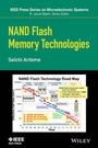
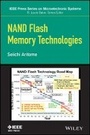
Figure 1.2 shows the memory hierarchy of computer system before mass production of NAND Flash. SRAM and DRAM had been used as cash memory and main memory, respectively. And magnetic memories, such as HDD, had been used as a nonvolatile mass-storage device. NAND flash memory had been targeted to replace magnetic memory [54]. Actually, from the production start of NAND flash memory in 1992, the NAND flash memory has been widely applied to new emerging applications and has replaced magnetic memory, as shown in Fig. 1.3. At first, a photo film had been completely replaced by the memory cards of NAND flash memory. Next, the floppy disk was replaced by USB drive memory. The mobile music equipment with cassette tape was replaced by the MP3 player using flash memory storage. Also, NAND flash memory had created new market of smartphones and tablet PCs. And now, the application is extending to the SSD (solid-state drive) market, not only for the consumer but also for the enterprise server. Therefore, over 20 years, NAND flash memory has created new large-volume markets and industries of consumer, computer, mass storage, and enterprise server. NAND flash production volume was tremendously increased. The overall NAND market is expected to reach $40 billion in 2016 [55]. NAND flash has become an explosive innovation and has greatly contributed to the improvement of our lives with the advent of convenient mobile equipment such as smartphones and tablet PCs.
FIGURE 1.2 Target market of NAND flash memory.
Table 1.1 shows the history of NAND flash memory development, based on technical papers from 1987 to 1997. During the 10 years from the first NAND flash paper in 1987, all of the fundamental and important NAND flash technologies were established, such as page programming [7, 8], block erase, the uniform program and uniform well erase scheme [9, 12, 13], bit-by-bit verify [15, 21], the ISPP (incremental step pulse program) [25, 26, 29], the self-aligned STI cell [22, 51, 56], the shield bit-line scheme [21], and so on. These technologies could satisfy the requirements of file storage memory.
Table 1.1 History of the NAND Flash Memory (~1997)
Year Authors References Conference/Journal 1984 Flash Memory, first paper F. Masuoka et al. [1] IEDM 1984 1987 NAND-type flash memory, 1st paper F. Masuoka et al. [2] IEDM 1987 1988 NAND-type flash memory R. Shirota et al. [3] VLSI 1988 Drain-FN program M. Momodomi et al. [4] IEDM 1988 1989 4-Mb NAND-type flash memory Y. Itoh et al./M. Momodomi et al. [5, 6] ISSCC1989/ JSSC Page program M. Momodomi et al./Y. Iwata et al. [7, 8] CICC1989/ JSSC 1990 Well erase reliability S. Aritome, et al [9] IRPS 1990 4-Mbit tight Vt distribution T. Tanaka et al./M. Momodomi et al. [10, 11] VLSI 1990/JSSC1991 Well erase R. Kirisawa et al. [12] VLSI 1990 Bipolarity program/erase S. Aritome et al. [13] IEDM 1990 Double patterning R. Shirota et al. [14] IEDM 1990 1992 Bit-by-bit verify T. Tanaka et al. [15] VLSI 1992 1993 Reliability of flash S. Aritome et al. [16] Proceedings of IEEE 0.4-µm 64-Mb-cell technology S. Aritome et al. [17,18] SSDM 93/ JJAP 1994 SILC H. Watanabe et al. [19] VLSI 1994 Cycling and data retention reliability S. Aritome et al. [20] IEICE Intelligent program, shield BL scheme T. Tanaka et al. [21] JSSC Self-aligned STI cell (SA-STI cell) S. Aritome et al. [22] IEDM 1994 1995 32-Mb NAND K Imamiya et al./Y. Iwata et al. [23, 24] ISSCC1995/ JSSC 32-Mb NAND with increment step program pulse (ISPP), self-boost K. D.Suh et al. [25, 26] ISSCC1995/ JSSC Read disturb, SILC S. Satoh, et al [27, 28] ICMTS1995/ED Increment step program pulse (ISPP) G. J. Hemink et al. [29] VLSI 1995 Double Vt select gate K Takeuchi et al. [30, 31] VLSI 1995/ JSSC SWATT cell S. Aritome et al. [32, 33] IEDM 1995/ ED 1996 128-Mb MLC T. S. Jung et al. [34, 35] ISSCC 1996/ JSSC 64 Mb J. K. Kim et...